
This is a documentation for my custom Pi Pico 2W made using Raspberry Pi's Hardware design with RP2350. Below you will find the pinout for this board, BOM and schematic. Everything can also be found in the github repo alongside test code and more.
Git repo :)
Buttons
- Bootsel button - press while plugging in to enable mass storage mode
- Run button - press to reset the board
Pinout
Boards Pinout
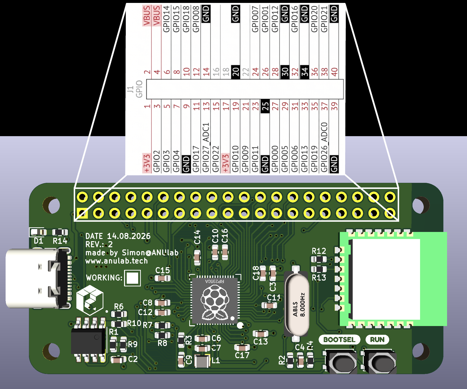
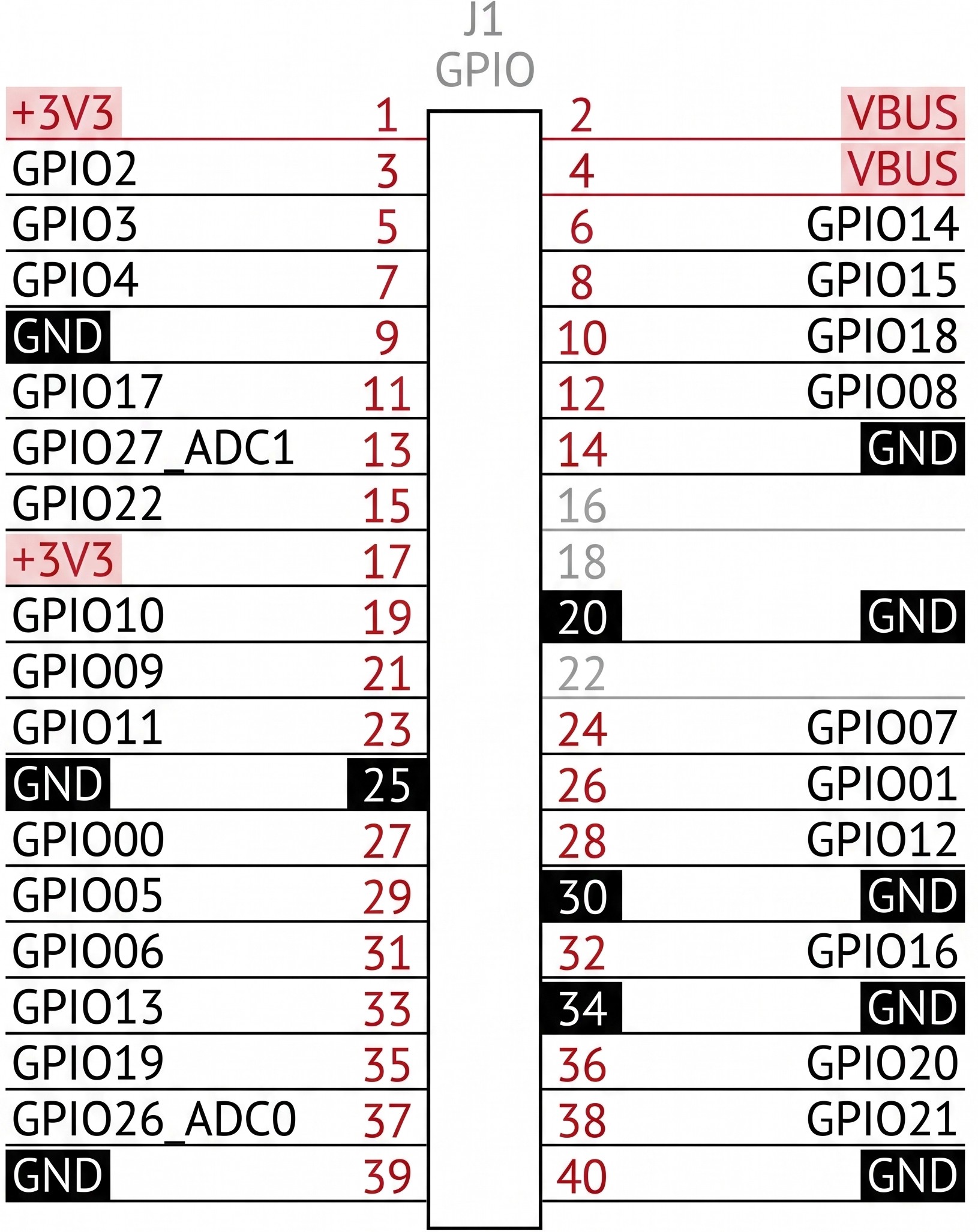 (Pinout assignment graphic generated using Google's Gemini)
BOM
BOM
| Reference | Value | Qty | Placement | Package | Notes |
|---|---|---|---|---|---|
| C1,C5,C19 | 10u | 3 | Back | 0603 | |
| C2,C8,C10-C18 | 100n | 11 | Front | 0603 | |
| C3,C4 | 15p | 2 | Front | 0603 | |
| C6,C7,C9 | 4.7u | 3 | Front | 0603 | |
| D1 | LED | 1 | Front | 0603 | |
| L1 | 3.3u | 1 | Front | - | AOTA-B201610S3R3-1 |
| R1 | 10k | 1 | Front | 0603 | DNP* |
| R2,R4,R6 | 1k | 3 | Front | 0603 | |
| R3,R14 | 33 | 2 | Front | 0603 | |
| R5,R11 | 5.1k | 2 | Back | 0603 | |
| R7,R8 | 27 | 2 | Front | 0603 | |
| R9 | 0 | 1 | Front | 0603 | DNP* |
| R10 | 0 | 1 | Front | 0603 | |
| R12 | 470 | 1 | Front | 0603 | |
| R13 | 10k | 1 | Front | 0603 | |
| X1 | 12MHz | 1 | Front | - | 12.00M-SDMH49S |
| U1 | 1 | Front | - | RP2350A | |
| U3 | 1 | Front | SOIC 8 | W25Q40EWSNIG | |
| U4 | 1 | Front | - | RMC20452T | |
| U5 | 1 | Back | SOT-223 | AMS1117-3.3 | |
| SW1,SW3 | 2 | Front | - | PTS815SJM250SMTR | |
| J1 | 1 | Front | - | 40-pin GPIO | |
| J2 | 1 | Front | - | Receptacle USB2.0 14P | |
| *(D)o (N)ot (P)opulate |