
This is a documentation for a development extension that I made for IcePi Zero FPGA. Below you can find a github repository of this project along side the kicad files and a demo code for IceStudio (if you are using IceStudio, make sure to have version 1.0 or later)
Git repo :)
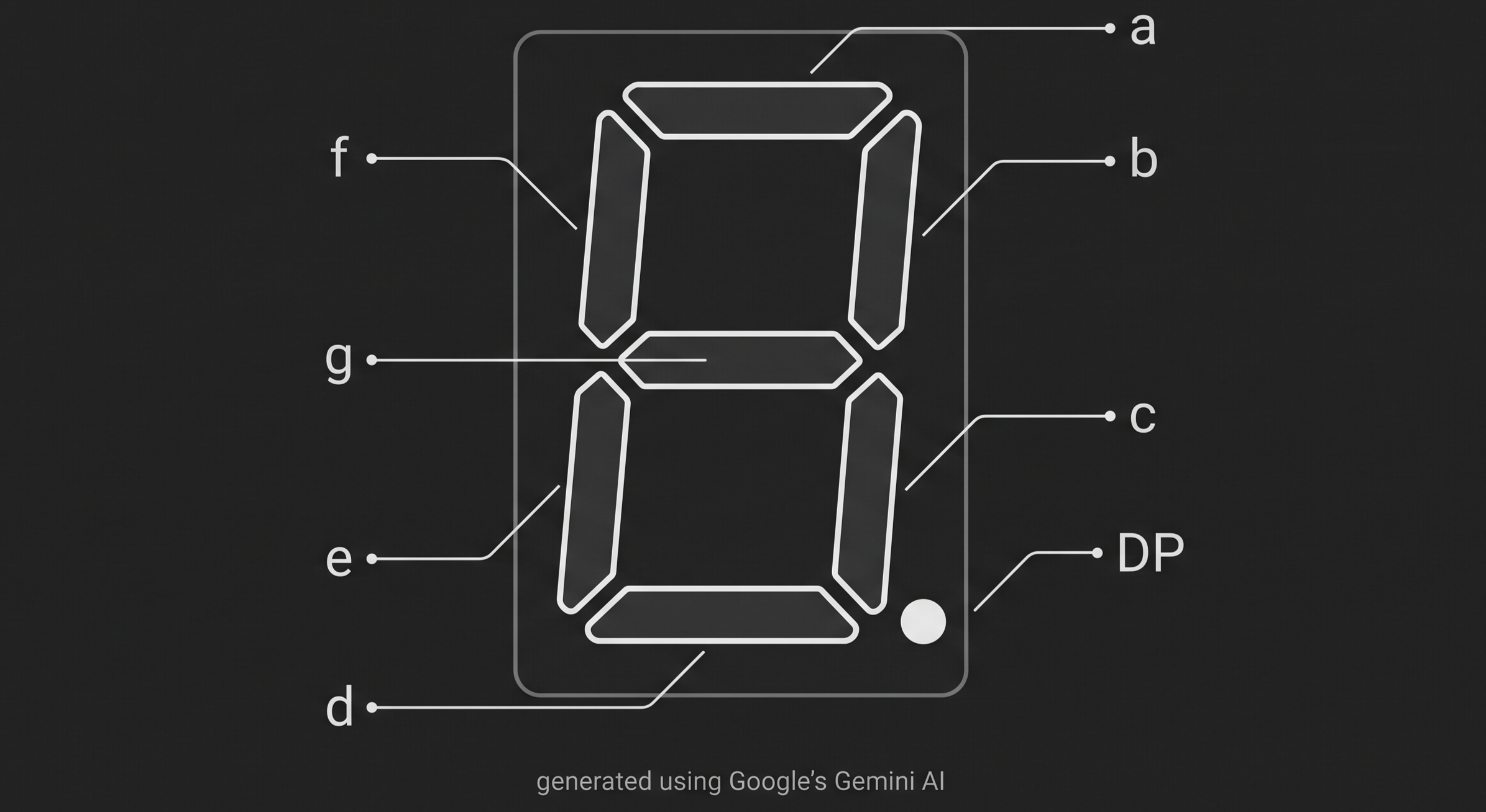
Pin Assignment
List of pins and components connected to them
| IcePiZero pin | Name on the dev board | Component |
|---|---|---|
| GPIO02 | IO2 | Display A* |
| GPIO03 | IO3 | Display B* |
| GPIO04 | IO4 | Display C* |
| GPIO05 | IO5 | Display D* |
| GPIO06 | IO6 | Display E* |
| GPIO07 | IO7 | Display F* |
| GPIO08 | IO8 | Display G* |
| GPIO09 | IO9 | Display dot* |
| GPIO10 | IO10 | Display anode 1 |
| GPIO11 | IO11 | Display anode 2 |
| GPIO12 | IO12 | Display anode 3 |
| GPIO13 | IO13 | Display anode 4 |
| GPIO14 | IO14 | LED - Blue |
| GPIO15 | IO15 | LED - Red |
| GPIO16 | IO16 | LED - Green |
| GPIO17 | IO17 | DipSwitch 1 |
| GPIO18 | IO18 | DipSwitch 2 |
| GPIO19 | IO19 | DipSwitch 3 |
| GPIO20 | IO20 | DipSwitch 4 |
| GPIO21 | IO21 | DipSwitch 5 |
| GPIO22 | IO22 | DipSwitch 6 |
| GPIO23 | IO23 | DipSwitch 7 |
| GPIO24 | IO24 | DipSwitch 8 |
| GPIO25 | IO25 | Button - Top right |
| GPIO26 | IO26 | Button - Left |
| GPIO27 | IO27 | Button - Bottom right |
*Displays pin asignment below (generated using Google's Gemini)
BOM
| Component | Value | Quantity | Notes | Component reference |
|---|---|---|---|---|
| 7 segment display with 4 digits | - | 1 | KW4-361ASB | U1 |
| SMD RGB LED | - | 1 | R5050RGBC-001 | LED1 |
| 8x dip switch | - | 1 | DM-08-V | SW2 |
| 5x5mm THT button | - | 3 | - | SW1, SW3, SW5 |
| 40pin goldpin plug | - | 1 | 2x20 female goldpin plug | J1 |
| Resistor | 10k | 11 | 0603 | R8-R10, R13-R20 |
| Resistor | 330 | 4 | 0603 | R1-R4 |
| Resistor | 22 | 1 | 0603 | R6 |
| Resistor | 10 | 2 | 0603 | R5, R7 |